IPC-2152 Standard: The Definitive Guide for PCB Trace Width Calculations
The IPC-2152 standard revolutionized PCB design by providing accurate methods for trace width calculation. This guide explains how to apply it using our PCB Trace Width Calculator.
Key Improvements Over IPC-2221
IPC-2152 introduced significant advancements:
-
More accurate thermal modeling
-
Consideration of board material properties
-
Experimental validation with modern materials
The Fundamental Equation
The core formula in IPC-2152 for internal layers:
Width (mm) = (Current × 0.024) / (TemperatureRise^0.44)Where our calculator automatically handles:
-
Current in Amperes
-
Temperature rise in °C
-
Copper weight adjustments
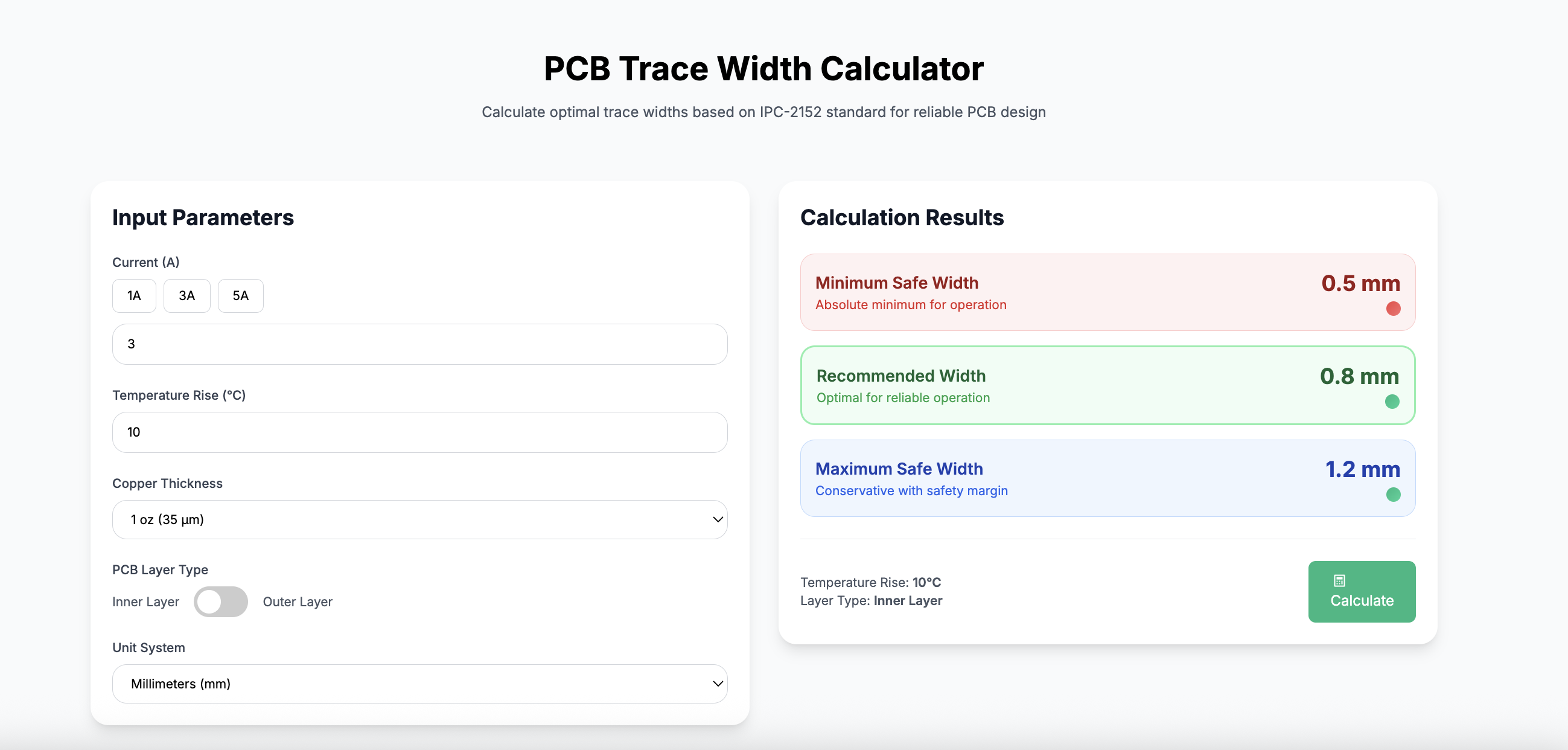
Practical Application
Example for a 5A power supply with 20°C rise:
1oz Copper
Width: 1.2mm
Using standard FR4 material
2oz Copper
Width: 0.84mm
30% reduction possible
Design Tip
Verify your calculations with our IPC-2152 compliant calculator before manufacturing.
Advanced Considerations
Parallel Traces
Multiple traces sharing current require spacing equal to their width
High Frequency Effects
Skin effect becomes significant above 10MHz
Via Current Capacity
Vias have different current limits than traces
Mastered IPC-2152? Try our advanced calculator features for complex designs.
Back to Blog