Practical Applications of PCB Trace Width Calculator in Modern Electronics
Proper trace width calculation is essential for reliable PCB designs. This article explores real-world applications of PCB trace width calculators across various industries.
Power Electronics Applications
In power electronics, accurate trace width calculation prevents overheating and ensures efficient current flow. Key considerations:
-
High current applications (10A+) require careful calculation
-
Thermal management impacts trace width requirements
Example: Motor Driver PCB
For a 15A motor driver with 20°C max temperature rise:
// Using our PCB Trace Width Calculator
Current: 15A
Temp Rise: 20°C
Copper: 2oz
Result: 3.2mm minimum width
Consumer Electronics
Space-constrained designs require balancing current capacity with PCB real estate:
Smartphone Charging Circuit
2A charging circuit with 10°C rise needs 0.5mm trace width
LED Driver Boards
High-efficiency designs often use multiple parallel traces
Industrial Applications
Harsh environments demand additional safety margins:
| Application | Safety Factor |
|---|---|
| Automotive | +30% width |
| Aerospace | +50% width |
Pro Tip
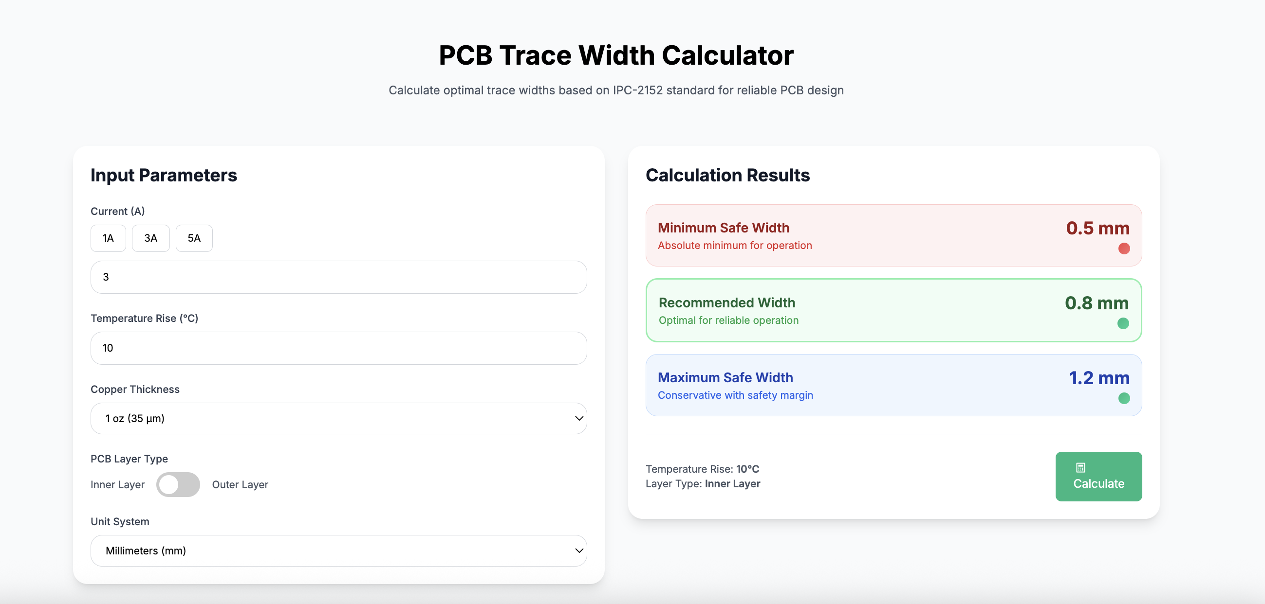
Always verify calculations with our interactive PCB Trace Width Calculator before finalizing designs.
Common Mistakes
Ignoring Temperature Rise
Leads to premature failure in high-current applications
Overlooking Copper Weight
2oz copper requires different calculations than 1oz
Ready to apply these principles? Use our PCB Trace Width Calculator for your next project.
Back to Blog